Printed circuit boards for LED signalling solutions
Today's world of lighting and electronics demands devices with ever smaller dimensions and ever-higher performance. Miniaturised printed circuit boards are the answer to these requirements, given their adaptability to multiple integrations and applications.
By combining LEDs soldered onto PCBs, it is possible to create state-of-the-art electronic products that can be used as lighting solutions for an increasingly wide range of purposes: from food equipment, including coffee machines, ovens, hoods and hobs, to vending machines.
A well-functioning lighting component mounted on a circuit board is the result of skilful PCB construction.
But what is a PCB? What is the function of printed circuit boards? Let's find out together in this in-depth study.
More specifically, we will talk about:
- PCB printed circuit boards: what they are
- Production of printed circuit boards: how it is done
- Printed circuit board program
- SLIM's offer of printed circuit boards
Interested in SLIM's products? Click on the link and download the general catalogue.
PCB printed circuit boards: what they are
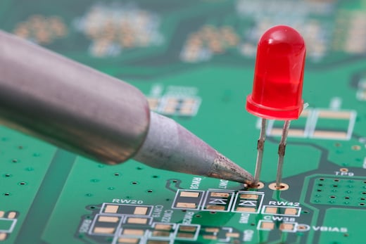
PCB stands for Printed Circuit Board, this term indicates the green, blue or red boards, usually rigid, on which the electronic components are assembled and then connected together through copper tracks. The function of PCBs is to provide mechanical support for the components and to allow them to be electrically connected via tracks or traces of conductive material.
The printed circuit board consists of a series of alternating layers of different types of materials which are laminated together with heat through a special adhesive process so that the end result is a single object.
This component is the basis from which the circuit board is subsequently formed through various manufacturing processes.
Production of printed circuit boards: how it is done
It is the designer who, on the basis of his initial idea, decides which technical characteristics a printed circuit board should have; this also takes into account the elements which will later be mounted on it.
The production of printed circuit boards consists of various stages which also vary in relation to the technology used to assemble the components on the board itself.
The manufacturing process will vary depending on whether THT or SMT technology is used. THT, Through Hole Technology, is the production method whereby the metal terminals of the electronic components are inserted directly into the metal holes on the circuit board. SMT, Surface Mounting Technology, on the other hand, involves mounting the electronic components directly on the surface of the fibreglass plate using specific machinery, including the Pick&Place machine.
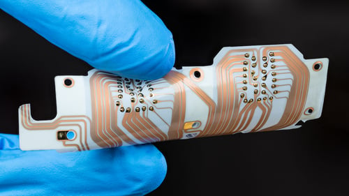
Regardless of the specific steps involved in the production of the circuit boards, one of the first aspects to take into consideration is the size and material of the circuit board. The production material of the PCB and its size will be selected according to the field of application. In most cases, glass fibre is used, which is a highly resistant and insulating compound that is perfect for guaranteeing optimum performance of the device. Depending on the production process and the type of substrate, the circuit is not only rigid, but can also be flexible, or composed of rigid and flexible sections. The difference depends on the compound and the thickness of the insulation material chosen.

Printed circuit board program
The first step in making a printed circuit board is the practical construction of a circuit diagram, which is done using a printed circuit board program. Printed circuit boards can be designed and programmed using production software. There are a number of specific PCB programs available: the choice of the right one to use is made on the basis of specific design requirementsstands for Printed Circuit Board, this term indicates the green, blue or red boards, usually rigid, on which the electronic components are assembled and then connected together through copper tracks. The function of PCBs is to provide mechanical support for the components and to allow them to be electrically connected via tracks or traces of conductive material.
In the specific case of the lighting sector, designers of PCBs for lighting applications also need to understand how to optimise the thermal behaviour of the designed component. In fact, the realisation of a PCB is not merely a matter of the design of the printed circuit, but must take into account a series of factors related to the management of the heat of the light source and the circuit, by means of appropriate heat sinks and thermal interfaces.

SLIM's offer with printed circuit boards
SLIM offers customised lighting solutions with printed circuit boards for different application areas. One of the best examples is the backlighting of knobs for ILVE's Panoramagic line of professional cooking systems. In order to achieve homogeneous light with a specific red hue and to facilitate assembly, an initial printed circuit board with high-performance LEDs was used. The satisfactory performance of this solution led to the subsequent development of a light guide with a customised metal ring.
Are you looking for a customised solution based on the use of printed circuit boards? Click on the button below and don't hesitate to contact us, our R&D team will be happy to help you find the solution that best suits your needs.
